Table of Contents
Aim/Aim of Experiment
To verify the Laws of Combination (Parallel) of Resistances using a Metre bridge.
Apparatus/Material Required
- A Meter bridge
- A Leclanche cell (Battery Eliminator)
- A Galvanometer
- A Resistance box
- A Jockey
- Two Resistance coils/wires
- A Set square
- Sand Paper
- Connecting wires.
Theory
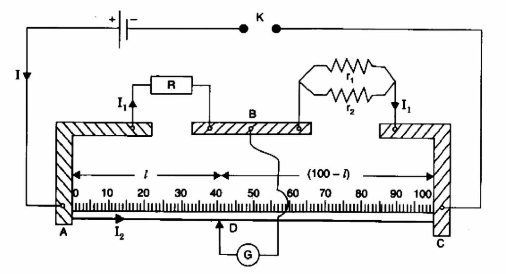
(i) The resistance (r) of a resistance wire or coil is given by r = (100-l)/L×R,
Where R is the resistance from the resistance box in the left gap and L is the length of the Meter bridge wire from zero end up to balance point.
(ii) When r1 and r2 are connected in parallel then their combined resistance is given by
RP = r1r2/r1+r2.
Circuit Diagram
Procedure
- Mark the two resistance coils as r1 and r2.
- To find r1 and r2 process same way as in experiment 2 (if r1 and r2 unknown).
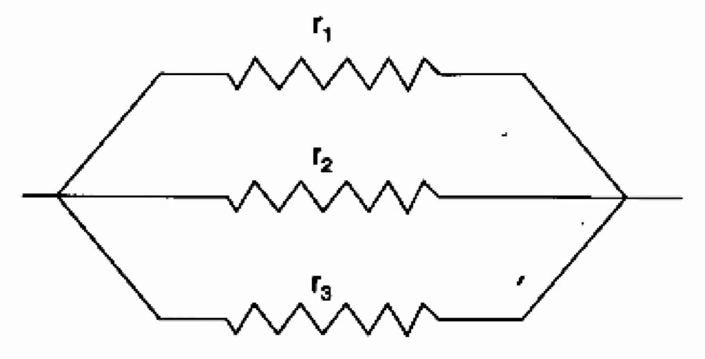
- Connect the two coils r1 and r2 in parallel as shown in figure in the right gap of Meter bridge and find the resistance of this combination, Take at least three sets of observations.
- Record your observations.
Observations
Value of r1:
| Resistance of R.B (ohm) | Balance L (cm) | (100-l) (cm) | [(100-l)*R]/L | Mean r1 |
|---|---|---|---|---|
| 0.5 | 59 | 41 | 0.347 | |
| 1 | 37 | 63 | 0.587 | 0.6393 |
| 2 | 33 | 67 | 0.985 |
Value of r2:
| Resistance of R.B (ohm) | Balance L (cm) | (100-l) (cm) | [(100-l)*R]/L | Mean r2 |
|---|---|---|---|---|
| 0.5 | 83.2 | 16.8 | 0.1009 | |
| 1 | 80.8 | 19.2 | 4.208 | 1.729 |
| 2 | 69.4 | 30.6 | 0.881 |
Value of r3:
| Resistance of R.B (ohm) | Balance L (cm) | (100-l) (cm) | [(100-l)*R]/L | Mean rp |
|---|---|---|---|---|
| 0.1 | 27 | 73 | 0.27 | |
| 0.2 | 32 | 68 | 0.42 | 0.36 |
| 0.5 | 56 | 44 | 0.39 |
Calculations
Calculations for verification of laws r1 and r2 in parallel:
- The Experimental value of Rp = 0.36 ohm.
- The Theoretical value of Rp = (r1r2)/r1+r2 = (0.693×1.729)/(0.693+1.729) = 0.4667 ohm.
- Experimental Error (Difference if any) = [(0.36-0.4667)/(0.36×100)] = 29.6%.
Result
Within limits of Experimental Error, Experimental and Theoretical values of Rp are same, Hence, low of resistances in parallel are verified.
Precautions
- The Connection should be neat, clean and tight.
- All the plugs in the resistance box should be tight.
- The wire should not make a loop.
- The key should be insert only while taking observations.
- Check source of error.
Sources of Error
- Resistance box, Instrument screw and other plugs may be loose.
- Unavailable thickness connecting wires.
- Wire may be make loop.
Viva Voice Questions with Answers
1. What is resistance?
Answer: The ratio of potential difference V across the ends of a conductor to the current I flowing through it. It is represented by R and is given by R=V/I.
2. List the factors affecting the resistance?
Answer: The factors affecting the resistance are,
- Length
- Material
- Area of cross-section
- The temperature of the conductors
3. What is the mathematical form of Ohm’s law?
Answer: V=IR
4. What is ohmic resistance?
Answer: The resistance which obeys ohms law is known as Ohmic resistance.
5. Give examples of non-ohmic resistance?
Answer: Transistors, vacuum tube diodes and semiconductor diodes.
6. Why do we use thick connecting wires?
Answer: Thick connecting wires offer negligible resistance compared to given alloy wire whose resistance is to be determined.
7. What is the material of the connecting wires used in the experiment?
Answer: Copper.
8. How does resistance change in parallel combination?
Answer: Resistance decreases in parallel combination.
9. Explain decrease of resistance in parallel combination.
Answer: In parallel combination, the effective area of cross-section increases. As R∝ 1/A resistance decreases in parallel combination.
10. What is Wheatstone bridge?
Answer: It is the arrangement of four resistance in quadrilateral form to determine one unknown resistance in term of other three resistances.
11. What is a metre bridge?
Answer: It is the practical form of Wheatstone bridge to determine the unknown resistance and resistivity of a given alloy wire.
12. Why is a metre bridge so called?
Answer: Since the bridge uses one metre long wire, it is called a metre bridge.
13. Why the bridge method for resistance measurement is better than Ohm’s Law?
Answer: It is so because the bridge method is a null method (at null point, there is no current flowing in galvanometer) and more sensitive.
14. Why the metre bridge is suitable for measuring moderate resistances?
Answer: Because, Wheatstone bridge is suitable for moderate values of resistances. Therefore, Meter Bridge is more sensitive for moderate values.
15. Why is Wheatstone bridge (or metre bridge) method considered unsuitable for the measurement of very low resistance and very high resistance.
Answer: (i) For measuring low resistance – All resistances and resistance of galvanometer should be f low. The end resistance and connecting wires become comparable to the resistance being measured and introduce error in the result.
(ii) For measuring high resistance – The resistance forming the bridge should be high and the current in the galvanometer reduces and it became insensitive.
Class 12 Physics Practicals:
- To Determine Resistance Per cm of A Given Wire by Plotting A Graph for Potential Difference Versus Current
- To Find The Resistance of A Given Wire Using The Metre Bridge and Hence Determine The Resistivity (Spacific Resistance) of It’s Material
- To Verify The Laws of Combination (Series) of Resistances Using A Metre Bridge
- To Compare The EMF of Two Given Primary Cells Using Potentiometer
- To Determine The Internal Resistance of A Given Primary Cell Using Potentiometer
- To Determine Resistance of A Galvanometer by Half-Deflection Method And To Find Its Figure of Merit
- To Convert The Given Galvanometer (of Known Resistance and Figure of Merit) Into a Voltmeter of Desired Range and To Verify the Same
- To Convert the Given Galvanometer (of Known Resistance and Figure of Merit) Into An Ammeter of Desired Range and to Verify the Same
- To Find The Frequency of The AC Mains With a Sonometer
- To Determine Angle of minimum Deviation for a given Prism by Plotting a Graph between Angle of Incidence & the Angle of Deviation
- To Determine Refractive Index of a Glass Slab Using a Travelling Microscope
- To Find the Refractive Index of a Liquid by Using Convex Lens and Plane Mirror
- To Find Focal Length of A Convex Mirror Using A Convex lens
- To Find the Focal length of A Concave lens Using A Convex lens
What is r1 and r2?
r1 is 1st resistor and r2 is the 2nd resistor.